SIMSOLID = Meshless FEA
Meshless FEA with SIMSOLID
SIMSOLID is an analysis software for structural problems designed specifically for engineers. By eliminating geometry meshing and simplification SIMSOLID dramatically reduces the amount of time and expertise required for even complex FEA.
Meshless and finite element analysis are rarely mentioned in the same sentence. For decades the general understanding is that you need to spend 80% of your effort on fine-tuning a mesh in order to get a good FEA result. This process is based on the underlying mathematics and the numerical method used for the prediction of how part or assembly behaves under certain conditions.
It's time for a Change
FEA was independently developed by researchers in different universities and industries to address structural mechanics problems related to aerospace and civil engineering. The development for use and applications started around the mid-1950s as papers by Turner, Clough, Martin and Topp [1956], Argyris [1957] and Babuska and Aziz [1972] show.
Download a Free Trial
of SIMSOLID
So why is the history important? Because the fundamentals of solving problems with mathematics using meshing were invented 75 years ago and advanced in the decades since then. Doesn’t it make sense that additional advancements in mathematics can further our understanding of how to solve these complex problems?
How SIMSOLID Works
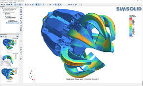
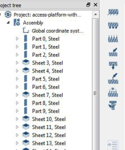
SIMSOLID can analyze large assemblies and complex parts that simply cannot be analyzed on a desktop computer with traditional FEA techniques. Using a multi-pass adaptive analysis, SIMSOLID controls solution accuracy.
The breakthrough extensions to the theory of external approximations are the basis for the SIMSOLID computational engine. External approximations are a generalization of Finite Element Method (FEM) in terms that:
- absolutely arbitrary geometrical shapes can be used as “finite elements”
- basis functions which approximate field of interest in the part volume can be of arbitrary class and are independent of the volume shape
SIMSOLID DOF are functionals with geometrical support in the form of volumes, areas, line clouds, and point clouds and SIMSOLID does not use the point-wise degrees of freedom (DOF) inherent in traditional FEA – providing the ability to handle geometrical imperfections, as well as assembly contact imperfections like gaps, penetrations and ragged contact areas.
SIMSOLID controls solution accuracy using multi-pass adaptive analysis. Adaptivity can be defined on a global or part local basis and adaptivity is always active. The SIMSOLID methodology is fast and efficient. It provides superior performance metrics for computational time and memory footprint that allow very large and/or complex assemblies to be solved quickly on desktop class PC’s.
Capabilities
Analysis Solutions
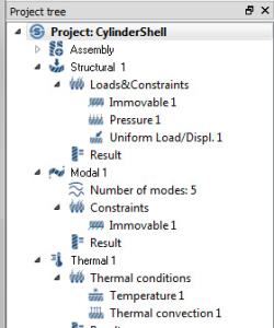
The following simulation types are supported: linear statics, modal, nonlinear statics (material & geometrical), thermal, coupled thermal-stress, linear dynamics (time, frequency and random response).
Supported Connections and Boundary Conditions
- Assembly Connections: Smart auto connections, bonded, sliding, separating with friction, bolted, spot & laser welds, fillet/seam welds, virtual connectors
- Loads & BC’s: Immovable constraint, sliding constraint, hinge constraint, enforced displacement, force, pressure, gravity, thermal, inertia relief, bolt/nut preload, dynamic loads, hydrostatic loads, bearing loads, and remote loads.
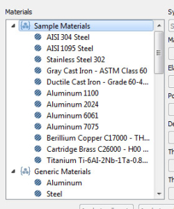
Material Properties
- Isotropic
- Incompressible
- Elastoplastic with NL stress vs strain curves
- Rigid
- User extensible
CAD Connectivity
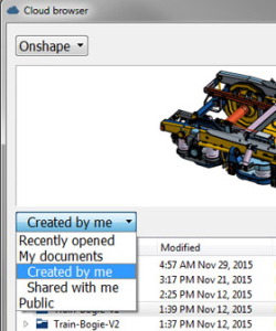
- Direct data integration to Cloud-based CAD systems
- Standard STL output from any CAD system
- Direct file support for mainstream CAD systems: CATIA, NX, Creo, SOLIDWORKS, Inventor and SolidEdge
- Direct file support for common neutral formats: STEP, ACIS and Parasolid, etc.
Post-Processing and Reporting
Result types:
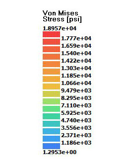
- Contour plots with displacements, stress & strains
- Deformed shape animation
- Max/min labels
- Point probes XY plots
- Reaction/contact forces
- Bolt/nut forces Spot weld forces
- Frequencies and mode shapes
- Modal participation factors
- Safety factors
Reporting:
- Image thumbnails and captions associated with model graphics state, part visibility, and results display
- Synchronized model and results browsing
- Results are exported as full resolution image files
General Usability
- Able to process mixed (SI and IPS) units
- Measurements (distance, ray probe, local coordinates)
- Global and local coordinate systems
- Default views (front, back, left, right, top, bottom)
- Custom saved views
Looking for Generative Design Software? Click Here to Try Altair Inspire
Simulation Types
- Linear Statics
- Modal
- Thermal
- Thermal Stress
- Geometric Nonlinear Statics
- Material Nonlinear Statics
- Dynamics time, frequency and random response
Geometry Sources
- Direct data integration to Autodesk Fusion 360, SOLIDWORKS and Onshape CAD systems
- Standard STL output from any CAD system
- Direct file support for mainstream CAD systems: CATIA, NX, Creo, SOLIDWORKS, Inventor and Solid Edge
- Direct file support for common neutral formats: STEP, ACIS and Parasolid, etc.
Material Properties
- Isotropic
- Incompressible
- NL stress vs strain curves
- Rigid
- User extensible
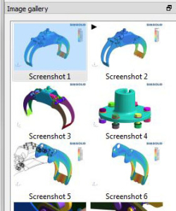
Gallery
Image thumbnails and captions associated with:
- Model graphics state
- Part visibility
- Results display
- Synchronized model and results browsing
- Exported as full resolution image files
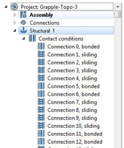
Assembly Connections
- Smart auto connections
- Bonded
- Sliding
- Separating
- Bolted
- Spot & laser welds
- Fillet/seam welds
- Virtual connectors
Boundary Conditions
- Prescribed:
- displacement
- pressure, force
- gravity
- temperature, flux
- convection
- volumetric heat
- Force at a remote point
- Hinge constraints
- Spring support
- Hydrostatic & bearing loads
- Inertia loads
Results
- Contour plots
- displacement
- stress
- strain
- Deformed shape animation
- Max/min labels
- Point probes
- XY plots
- Reaction/contact forces
- Bolt/nut forces
- Spot weld forces
- Modal participation factors
- Safety factors