Navigating Meshing Issues in Creo Flow Analysis: A Workaround for the CFA Community

Over the past few weeks our engineers have spent time with the latest version of Creo Flow Analysis in Creo 7 and we’re always keeping an eye out for issues our customers may run into. In this case we found a serious issue and want to share a workaround with the CFA community.

When creating CFA projects from Creo assemblies the meshing process regularly failed with a rather cryptic traceback. After some experimentation we found that this can be easily avoided by creating a CFA project with only the extracted volume part.

To do this generate your extracted fluid volume as normal with the assembly, then identify the name of that part. In file explorer navigate to your assembly folder and copy the same part into a new directory, this will be your CFA directory moving forward. Open the part by itself in Creo and create a new CFA project. The fluid volume has already been extracted so it can be directly specified as the fluid volume.

PTC has informed us that this bug will be corrected in a future release of Creo 7 but in the meantime I hope this will be helpful!


Navigating Meshing Issues in Creo Flow Analysis: A Workaround for the CFA Community

Over the past few weeks, our engineers have diligently explored the latest version of Creo Flow Analysis in Creo 7. As always, we strive to identify and address any potential issues that our customers might encounter. Recently, we discovered a significant problem during the meshing process and want to share a practical workaround with the CFA community.

The Problem: Meshing Failures in CFA Projects

When creating CFA projects from Creo assemblies, our team noticed that the meshing process frequently failed, generating a cryptic traceback error. This issue can be quite frustrating, especially when dealing with complex assemblies. After extensive testing and experimentation, we pinpointed the cause of the problem and found an effective way to circumvent it.

The Workaround: Using Extracted Fluid Volume

To avoid meshing failures, we recommend creating a CFA project using only the extracted fluid volume part. Here’s a step-by-step guide to implement this workaround:

  1. Generate the Extracted Fluid Volume: Start by generating the extracted fluid volume as you normally would with your assembly. Ensure that you correctly identify and name the extracted fluid volume part.
  2. Copy the Part to a New Directory: Using your file explorer, navigate to your assembly folder and locate the extracted fluid volume part. Copy this part into a new directory, which will serve as your dedicated CFA directory for this project.
  3. Open the Part in Creo: Open the extracted fluid volume part by itself in Creo. Do not open the entire assembly—just the single part that represents the fluid volume.
  4. Create a New CFA Project: With the part open in Creo, create a new CFA project. Since the fluid volume has already been extracted, you can directly specify this part as the fluid volume for your new CFA project.

Looking Ahead

PTC has acknowledged this bug and informed us that it will be corrected in a future release of Creo 7. Until the official fix is available, we hope this workaround proves helpful to our fellow engineers and the broader CFA community. Implementing this method should streamline your workflow and minimize disruptions during the meshing process.

Conclusion

We are committed to supporting our customers and enhancing their experience with Creo Flow Analysis. By sharing this workaround, we aim to provide immediate relief from the meshing issues while awaiting a permanent fix from PTC. Stay tuned for more updates and tips as we continue to explore and optimize the latest features in Creo 7.

Hitachi Automotive Systems, LTD. discusses Particleworks

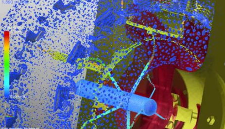
“Responding to the requirement to evaluate cooling performance, Particleworks had become one of the candidates for simulation. We had used FVM (Finite Volume Method) based grid method CFD software already, and we decided to choose the more effective one by comparing the time for pre-processing and calculation speed. Simulation of the piston oil jet shows that it is unsteady, the solid region moves, and the oil occupancy in the analysis region is small. Therefore, in FVM, oil was represented by VOF (Volume of Fluid) and solid movement was controlled by morphing the remeshing based on the movement profile written in text. On the other hand, in Particleworks, oil was represented by particles, and solid movement was controlled only by the movement profile. First, we compared the time for pre-processing. It took considerable amount of time to simplify the CAD model in FVM. It meant reducing the number of meshes and simplifying fine edges, and fillets required a lot of time and effort. Such a simplification process is often necessary with the grid method in order to avoid mesh breakage when using morphing. After that the process with meshing macro creation of moving boundaries, setting of analysis conditions, and trial calculation. At this time, the CAD model was not sufficiently simplified, and the mesh was broken during the trial calculation, which caused additional man-hours to simplify the CAD model again. In contrast, Particleworks does not use meshes, so there is no need to simplify the CAD model, which saves a lot of time. In Particleworks, a shape that maps the particle values is required when evaluating the average heat transfer coefficient of the cooling channel. So, we took time to make the patch area of this shape uniform in advance. Nevertheless, when comparing the total time for pre-processing, Particleworks resulted in less than 1/3 of FVM’s” Read the full interview here: https://enginsoftusa.com/pdfs/Hitachi-automotive-CFD-Particleworks.pdf

-Hitachi Automotive Systems, LTD.

FEV Oil-Cooled eMotor for Electric Drive Unit: A Case Study

Overview

In the ever-evolving field of electric vehicle technology, optimizing the efficiency and performance of electric drive units is paramount. One of the leading innovations in this area is the development of oil-cooled electric motors (eMotors). This case study focuses on the collaboration between FEV and Particleworks, showcasing how advanced simulation methodologies can significantly enhance the performance and reliability of electric drive units.

Particleworks Simulation Methodology

Particleworks leverages a cutting-edge, mesh-free simulation technique known as the “Moving Particle Simulation” (MPS) methodology. Unlike traditional simulation methods that rely on complex meshing processes, MPS uses particles to represent fluid and thermal phenomena. This approach allows for more flexible and accurate modeling of complex fluid dynamics, making it particularly suited for applications such as oil flow distribution and heat transfer in electric motors.

Benefits of Particleworks in eMotor Development

  1. Rapid Prediction of Oil Flow Distribution:
    • Particleworks enables engineers to quickly and accurately predict how oil will flow through the electric motor. This is crucial for ensuring that all components receive adequate lubrication, which is essential for reducing wear and prolonging the motor’s lifespan.
  2. Efficient Heat Transfer Analysis:
    • The ability to simulate heat transfer processes allows for the optimization of cooling strategies. By understanding how heat is dissipated within the motor, engineers can design systems that maintain optimal operating temperatures, thereby enhancing performance and preventing overheating.
  3. Power Loss Minimization:
    • Particleworks also helps in identifying and minimizing power losses. By analyzing the interaction between the oil and moving parts, engineers can develop designs that reduce friction and improve overall efficiency.

FEV’s Application of Centrifugal Oil Cooling

In this case study, FEV utilized centrifugal oil cooling to significantly enhance the performance of their electric drive unit. This innovative cooling method provides several key benefits:

  • Faster Recovery Post Peak Torque Operation:
    • Centrifugal oil cooling ensures that the motor can quickly return to optimal operating temperatures after running in the peak torque region. This rapid recovery is crucial for maintaining performance and reliability during high-demand periods.
  • Increased Power Output and Torque:
    • By effectively managing heat and lubrication, FEV was able to achieve a remarkable 50% increase in both power output and torque. This substantial improvement underscores the effectiveness of oil cooling in enhancing the capabilities of electric drive units.

Conclusion

The collaboration between FEV and Particleworks exemplifies the potential of advanced simulation methodologies in driving innovation in electric vehicle technology. By leveraging the MPS methodology, engineers can gain deeper insights into fluid dynamics and thermal processes, leading to more efficient and powerful electric motors.

This case study highlights the significant advancements that can be achieved through the application of state-of-the-art simulation tools and innovative cooling techniques. For a more detailed understanding of the methodologies employed and the results obtained, you can read the full case study here: FEV Oil-Cooled eMotor Case Study.

By exploring this case study, engineers and researchers can gain valuable insights into the design and optimization of oil-cooled electric motors, paving the way for further advancements in electric drive technology.

CFD testing of HeartAssist® LVAD performance under realistic working conditions

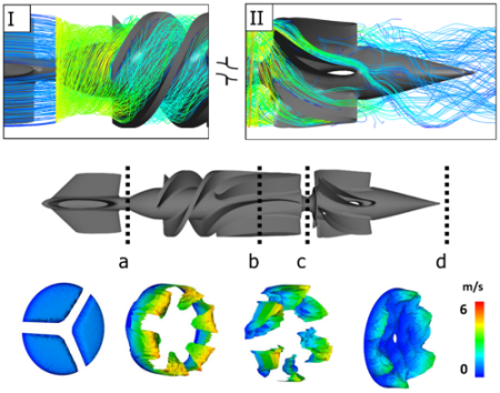
VADs are increasingly used to mitigate the shortfall in donor organs for cardiopathic patients awaiting heart transplants annually by providing a bridge-to-transplant, or to stabilize patients with congestive heart failure. While rotary VADs have smaller dimensions and simpler structures than pulsatile VADs, their continuous, high-speed, rotating blood-flow patterns represent a potential risk factor to patients from thrombus formation, thromboembolic complications or device malfunction due to pump thrombosis. Pump thrombosis is one of the main causes for device malfunction, and patients are exposed to the risk of sudden death or the risks involved in complex device replacement surgery. In this work, computational fluid dynamics (CFD) simulations were performed to mimic the realistic operative conditions of the VAD HeartAssist 5® (HA5, ReliantHeart Inc., USA). CFD analysis can be exploited to predict blood flow streamlines passing through these devices. Read the full case study here: https://enginsoftusa.com/CFD-Consulting-Medical-Ventricular-Device.html

EnginSoft and the European Space Agency investigate hydroponic plant growth for future space missions

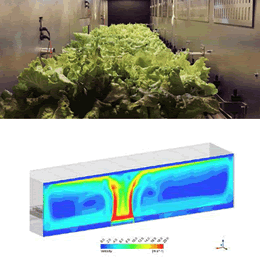
EnginSoft has been collaborating with the European Space Agency (ESA) for the past ten years, working actively in the MELiSSA program. At present, this project’s main efforts concern the life support system sector and the idea of creating an artificially closed ecosystem that generates food and oxygen for space crews on longterm missions. The current MELiSSA Pilot Plant (MPP), built to monitor the progress towards the goal, is located at the Universitat Autònoma de Barcelona. A 5-meter plant growth chamber, able to cultivate 100 plants and investigate their growth process, has been installed At the MPP, the Air and Canopy Subcompartment Analysis (ACSA) project was implemented to study the impact of airflow on hydroponically grown lettuce crops. Objectives The main objectives of this project were: – To improve the conditions in the growth chamber by reengineering the air management system; – To investigate the impact of airflow on plant growth. Computational Fluid Dynamics (CFD) Model of the system before the project The 5-meter plant growth chamber was replicated using a CFD model of the complete system. This model provided deep insight into the air distribution and the local environmental conditions around the aerial part of the plants

Ergonomic Simulation: Enhancing Company Competitiveness and Productivity

Overview

Ergonomic simulation is a powerful tool that can significantly enhance company competitiveness and boost productivity. By focusing on the well-being and comfort of employees, companies can foster a more motivated and efficient workforce. This approach involves designing workplaces that meet ergonomic standards, ensuring that employees can perform their tasks comfortably and without pain.

Importance of Ergonomics in the Workplace

A satisfied employee is a productive employee. When workers are comfortable and free from physical strain, they are more likely to be focused, motivated, and efficient. Ergonomically designed workplaces contribute to this by minimizing the risk of injury and discomfort. This not only improves individual performance but also has a positive impact on overall company productivity.

Benefits of Ergonomic Simulation

  1. Enhanced Employee Satisfaction: Ergonomic simulation helps identify potential issues in workplace design that could lead to discomfort or injury. By addressing these issues, companies can create a more pleasant working environment, leading to higher employee satisfaction.
  2. Increased Productivity: When employees are comfortable, they can work more efficiently and with greater focus. Ergonomic simulation allows companies to optimize workplace performance, unlocking reserves of productivity that might otherwise remain untapped.
  3. Long-Term Productivity Gains: Investing in ergonomic design has long-term benefits. It reduces the likelihood of work-related injuries and absenteeism, ensuring that employees can maintain high levels of productivity over time.

How Ergonomic Simulation Works

Ergonomic simulation involves using advanced software to model and analyze workplace environments. This technology can simulate various aspects of the workplace, including the physical layout, the interaction between employees and their workstations, and the potential strain on different parts of the body. By analyzing these factors, companies can make informed decisions about how to improve their workspaces.

Case Study: Vivelab Ergo

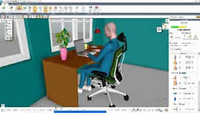
A detailed case study on Vivelab Ergo illustrates the impact of ergonomic simulation on workplace design and productivity. The study demonstrates how Vivelab Ergo used ergonomic simulation to identify and address issues in their workplace, leading to significant improvements in employee comfort and productivity.

  • Identifying Problem Areas: The simulation highlighted areas where employees were experiencing discomfort or strain. This allowed Vivelab Ergo to make targeted improvements to their workplace design.
  • Implementing Solutions: Based on the findings from the simulation, Vivelab Ergo made several changes to their workplace layout and equipment. These changes included adjusting workstation heights, redesigning seating arrangements, and improving lighting conditions.
  • Measuring Impact: After implementing the changes, Vivelab Ergo saw a noticeable increase in employee satisfaction and productivity. The simulation provided a clear roadmap for creating a more ergonomic and efficient workplace.

Conclusion

Ergonomic simulation is a valuable tool for any company looking to enhance its competitiveness and productivity. By prioritizing employee comfort and well-being, companies can unlock significant productivity gains and create a more motivated workforce. The case study on Vivelab Ergo highlights the tangible benefits of this approach, demonstrating how ergonomic simulation can lead to long-term improvements in workplace performance.

For a more detailed understanding of how ergonomic simulation can benefit your company, read the full case study here: Ergonomic Simulations – Vivelab Ergo Case Study.

This comprehensive document offers insights into the methodologies employed, the results obtained, and the positive impact on employee satisfaction and productivity. By embracing ergonomic simulation, companies can create healthier, more efficient work environments that drive success.

Flow field optimization of a medical device

CAE is highly effective for product optimization. In this technical article, we describe how a hybrid method of computational fluid dynamics analysis was used to enhance the design of a medical device to improve its ability to maintain a stable microclimate around a patient, but also to reduce both the computational efforts and the time required to obtain these results. A microclimate requires the maintenance of specific values of temperature, humidity and air velocity around a patient.

One of the validated designs turned out to be very promising, as it obtains a further reduction of the heat loss compared to the best design of the NSGA-II first phase design optimization: a further 4% gained. As expected, this has been achieved by a solution that stays close to the limit value on the patient’s temperature and humidity, but still keeping a good margin from the assigned constraint value of 0.025. Read the full case study here: https://enginsoftusa.com/CFD-Consulting-Medical-Airflow.html

Design and Analysis of Chain Drives made easy by RecurDyn Multi-Body Software

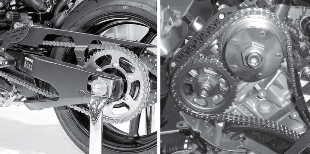
Chain models are among the largest and most complex that can be simulated with multi-body technology. First, depending on the chain length, the number of moving bodies could become remarkable. Second, contacts disturb the solution all over the chain, causing continuous impulsive excitation of the mechanism. Third, chain links are bodies with reduced inertia, whose motion is driven by stiff contacts and stiff bushings. RecurDyn has built its reputation on chain application. The main reason is its hybrid solver, which uses an innovative approach with respect to its competitor. Even chain models featuring hundreds bodies and thousands contact points can be simulated in a reasonable time. Read the full case study here: https://enginsoftusa.com/pdfs/RecurDyn-Multibody-Dynamics-Chain-Analysis.pdf

Dana’s Use of a New Validated Approach for Advanced Design of Powertrain

Overview

Dana Incorporated, a leading supplier of automotive powertrain components, is renowned for the exceptional capabilities and value of their products. To maintain their competitive edge and continue delivering top-notch products, the Advanced Methods group at the Dana Technical Center continually seeks innovative technologies to enhance their engineering and design processes.

Exploring Innovative Technology

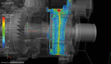
In 2015, the team at Dana embarked on an evaluation of Particleworks, a cutting-edge simulation tool designed to predict fluid dynamics in complex systems. Their goal was to determine the efficacy of Particleworks in predicting the accumulation of oil on the surface of a rotating component within one of their axle assemblies.

Particleworks: A Mesh-Free Simulation Tool

Particleworks utilizes the Moving Particle Simulation (MPS) methodology, a mesh-free approach that allows for the precise simulation of fluid behavior in dynamic systems. This technology is particularly advantageous for modeling scenarios involving complex movements and interactions, such as those found in automotive powertrains.

Application and Results

Dana’s evaluation focused on an axle assembly, specifically examining the oil accumulation on the spinning wheel located on the right side of the assembly. The study included side and top views of the component to comprehensively assess Particleworks’ predictive accuracy.

  • Side View Analysis: The top images in the study illustrated the side view of the axle assembly. Particleworks successfully predicted the pattern of oil accumulation, demonstrating a close match to the behavior observed in actual physical tests.
  • Top View Analysis: The bottom images provided a top-down perspective, further validating the simulation tool’s accuracy in replicating real-world oil behavior.

Validation and Implementation

The validation of Particleworks’ predictions against physical test results was a significant milestone for Dana. The close alignment between simulated and actual oil accumulation patterns confirmed the reliability of Particleworks as a simulation tool. This success encouraged Dana to integrate Particleworks into their engineering processes, enabling more precise and efficient design of their powertrain components.

Benefits and Future Prospects

By adopting Particleworks, Dana has enhanced its ability to accurately predict fluid dynamics within their powertrain systems. This has several key benefits:

  • Improved Design Accuracy: The ability to simulate oil behavior with high precision allows for more accurate and reliable component designs.
  • Reduced Development Time: Simulations can identify potential issues early in the design process, reducing the need for extensive physical prototyping and testing.
  • Cost Savings: With fewer prototypes and more efficient design iterations, the overall cost of product development is significantly lowered.
  • Enhanced Product Performance: Accurate simulations lead to better-performing components, ultimately resulting in higher-quality products for Dana’s customers.

Conclusion

Dana Incorporated’s successful implementation of Particleworks exemplifies the transformative impact of advanced simulation tools on the automotive industry. By leveraging the capabilities of Particleworks, Dana has not only improved their design processes but also set a new standard for innovation and precision in powertrain engineering.

For a detailed account of Dana’s evaluation and the benefits of using Particleworks, read the full success story here: Dana’s Success Story.

This case study provides valuable insights into how cutting-edge simulation technology can drive advancements in automotive design and engineering, ensuring that companies like Dana remain at the forefront of the industry.

Intermarine Shipyard tests Flownex SE for its naval piping systems

There are various piping systems that convey many different fluids on board a vessel. Each fluid must reach its user at the right pressure and flow conditions. Accessories such as valves, bends, fittings and pipes induce pressure losses (as a result of factors such as pressure (p), flow rate (q) and pipe size (diameter, A)). The designer has to calculate these probable pressure losses in the pipeline in order to select (or verify) the size of the pump to be installed in the piping system to prevent a number of possible problems. Usually, these calculations to predict pressure losses are performed “manually” using the procedures described in the technical literature, such as the method of equivalent lengths, with the help of software such as Microsoft Excel or similar, and with the lengths and the fittings information being derived from one-line diagram (2D CAD software). The Shipyard wanted to test the capability of the 1-D computational fluid dynamics (CFD) software known as Flownex Simulation Environment (SE), provided by EnginSoft S.p.A., as a pipeline solver for its naval piping systems. Read the full case study here: https://enginsoftusa.com/pdfs/Flownex-piping-design.pdf