Dynamic analysis of a Variable Displacement Oil Pump shaft under crankshaft torsional vibrations and internal pressure evaluated via CFD
This paper deals with an activity carried out at the Calculation & Simulation Department in Pierburg Pump Technology Italy SpA. The subject of analysis is a vane oil pump for truck applications. This product represents new generation oil pump in automotive industry thanks to the possibility to reduce the displacement at high engine speed for fuel save consumption. Aim of this study is the calculation of dynamic torque applied to pump shaft in order to have a better understanding about the causes of unfitting failures between rotor and pump shaft revealed in aggressive durability tests.
Product presentation
Variable displacement oil pumps represent a significant contribution for fuel saving capability in automotive industry. In comparison to conventional gerotor pumps, they have the possibility to optimize the oil flow according to engine demand, with a significant reduction of power absorption. The oil flow rate of a vane pump, such as that of a general volumetric pump, depends on its actual displacement, i.e. the difference between the maximum and minimum trapped volumes. This difference is a function of the pump eccentricity that is defined as the distance between the rotor axis (which is fixed) and the control ring axis. That's why, in order to obtain the displacement variation in this kind of pumps, the control ring is made to slide in housing.
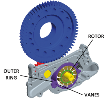
Fig. 1 - Assembly (rear view)
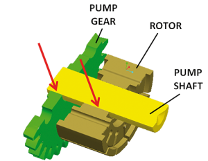
Fig. 2 - Pressfitted areas
The variable displacement oil pump considered in this study is driven by a train of three gears (Figure 1): engine gear (in blue), idle gear (in red) and pump gear (in green). Both pump gear and rotor are fixed to pump shaft by two different press fitting areas (Figure 2).
Procedure
In order to reach the target of calculation (dynamic torque on pump shaft) a multibody model was created taking care about driving action by crankshaft and braking actions due to pressure distribution inside the pump itself. The entire geometry has been imported by existing 3D-CAD model. Crankshaft motion has been imposed including its torsional vibrations, which is a fast dynamic function. This required a dedicated experimental activity on instrumented engine. Forces elements have been applied on each vane as a function of angular position. Angular history of hydraulic pressure has been calculated by means of CFD-simulation in working conditions where uncoupling between rotor and shaft has been observed during durability tests.
Setting of contact parameters is critical in this kind of analysis because the response of system is highly influenced by this. In this work contact parameters have been set up basing on a dedicated static structural FEM simulation where stiffness of gear contact has been evaluated. Scheme in Figure 3 shows the workflow of the entire activity. Aim of this study is the calculation of applied dynamic loads on pump shaft under crankshaft torsional vibration and internal hydraulic pressure evaluated via CFD. Resulting maximum instantaneous loads will be compared to ones obtained on experimental tests (see the specific paragraph) in order to understand if the dynamic of the system can explain by itself the reason of uncoupling failure between rotor and shaft.
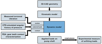
Fig. 3 - Workflow
Data acquisition
The implementation of crankshaft torsional vibrations into dynamic multibody model required dedicated experimental activity on engine that has been conducted by the customer. Full map of acquisition data has been collected on engine instrumented with employed sensors. Real rotation of crankshaft has been measured with respect to the ideal rotation. Ideal rotation is the imaginary position that crankshaft should have moving at constant speed.
FEM model
FE analysis has been conducted in order to numerically evaluate the stiffness properties on contact tooth-tooth. Target is to obtain the existing law between contact force and gear axis rotation, as characterization of contact stiffness. Special features have been built in order to obtain idle gear and pump gear with one single tooth (Figure 4). This choice has been done in order to guarantee a unique contact between a couple of teeth. In this model pump gear axis has been fixed-constrained and idle gear axis has been left free to rotate around its axis. A ramp of crescent torque up to 100 Nm has been applied to idle gear. The relative axis rotation has been post processed.
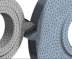
Fig. 4 - Single-tooth contact in idle and pump gears
The resulting contact law is shown in Figure 5. Stiffness behavior calculated by FE analysis has been reproduced in multibody environment. Obviously, stiffness behavior in FE analysis uses a different approach with respect to stiffness behavior in multibody software that on the contrary uses rigid bodies. Despite of this, it is important that the law between contact force and axis rotation has been maintained.
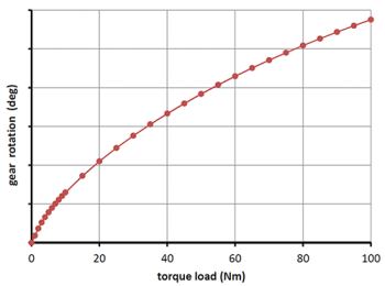
Fig. 5 - Resulting contact stiffness
CFD model
The CFD simulation has been completed in Simerics Pumplinx environment. To setup the model, four distinct oil volumes have been extracted with a Boolean operation of subtraction: inlet volume, outlet volume, suction pipe volume and rotor chambers volume. Result of the operation is presented in Figure 6.
Importing as STL files these volumes into Pumplinx software, the final CFD mesh has been created for the analysis (Figure 7). A realistic axial clearance has been simulated in the final mesh in order to suit the simulation closer to reality. CFD analysis has been setup in the requested engine operating condition at high temperature representing the performed durability tests during which the uncoupling between shaft and rotor has been observed.
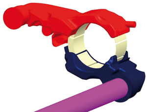
Fig. 6 - All oil volumes needed for CFD
To suit the simulation closer to reality for the durability test on engine, a defined aeration level of oil has been simulated. In fact because of the presence of air and/or vapor bubbles in oil, bubbles can implode due to the increase of local pressure when a rotor chamber is connecting to delivery side. CFD simulation has been set up as a transient analysis with moving mesh. Hexahedral elements have been used because they are most efficient elements for long thin geometries. In addition, it is the most efficient flexible mesh in case of needed mesh deformation to allow a better squeezing of the elements due to the rotation of the rotor. A monitor point has been placed in one rotor chamber and, because rotor is rotating, the point is rotating with it. After few initial iterations to reach convergence, variation of pressure and gas volume in the pocket with the rotation angle can be post-processed. This CFD derived pressure load has been used as input data into the following multibody model of the pump.
Multibody model
A multibody model of the pump has been implemented (Figure 8). Inertia properties for the bodies have been obtained on the basis of 3D CAD drawings and technical data.
By geometrical point of view, the case of medium backlash has been modeled. Each gear has been connected to chassis by revolute joints. Rotational degree of freedom only is allowed for each gear. The kinematic of multibody model has been built focusing on the reproduction of torsional behavior of the real mechanism. Gear transmission has been guaranteed by solid contact elements; they consist on an equivalent spring-damper element which law is based on overlap volume due to rigid teeth penetration. Preliminary multibody model has been built in order to set up contact parameters. In this model special features of single-tooth gears (Figure 4) have been imported as in the previous FE analysis.
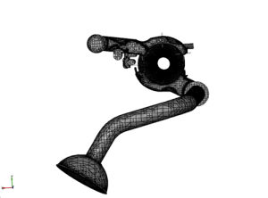
Fig. 7 - Mesh of the pump oil volumes
A loop of iterative simulations has been run until the same stiffness law in Figure 5 has been matched. Once the set up phase is terminated, the contact settings have been frozen and maintained in subsequent simulations where gears realize multiple contact. Hydraulic pressure effect has been modeled by force elements applied on each vane. Pressure level depends on rotor angular position and, as previously explained, has been calculated via CFD-simulation. In this analysis additional torsional loads have been modeled (representing frictional and viscous effects) in order to match experimental adsorption data.
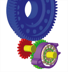
Fig. 8 - Multi-body model
Experimental tests
Experimental activity has been conducted in PPT testing department. Special fixture has been built in order to measure the disassembling torque and disassembling force between rotor and shaft under hydraulic press load. Obviously the unfitting loads are dependent by the real interference level on the coupling rotor-shaft. Extreme loads of the range refer to the condition of max and min interference. In the following table the minimum level is normalized to one:
Measured disassembling torque
1 ÷ 2.38 (normalized values)
Measured disassembling axial force
1 ÷ 1.82 (normalized values)
Results
Several events of rotor unfitting occurred during severe endurance tests on engine as shown in Figure 9. In this work it has been built a multidisciplinary model in order to evaluate if considered external actions themselves can explain the causes of rotor disassembling.
Forcing actions on dynamic system are mainly represented by crankshaft torsional vibration and hydraulic pressure. By the frequency content analysis of dynamic response it has been possible to assert that in this specific case the dynamic imposed by hydraulic internal pressure is dominant with respect to crankshaft vibrations.
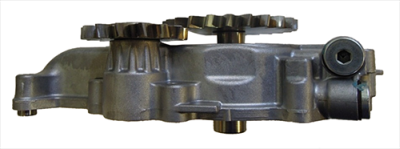
Fig. 9 - rotor decoupling
At least, simulation result of max instantaneous torque and axial force between rotor and shaft has been post processed. In the following table the minimum level is normalized to one:
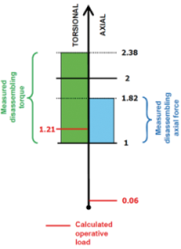
Calculated torque 1.21 (normalized value)
Calculated axial force 0.06 (normalized value)
Calculated loads have been compared to experimental data both in torsional direction (range 1÷2.38) and axial direction (range 1÷1.82). Calculated max instantaneous torque is higher than the minimum measured value (1.21 > 1). So it is probable that considered external actions (torsional vibrations and hydraulic pressure profile) are sufficient to explain the disassembling of rotor from its axis. Considering axial direction, calculated force is not critical because it is much lower than measured one (0.06 << 1). So in axial direction modeled loads are not sufficient to explain rotor unfitting.
Conclusions
In the application presented in this paper and for considered working conditions, the contribution of hydraulic internal pressure on the dynamic of system is dominant with respect to the contribution due to the presence of crankshaft torsional vibrations.
Main result of the whole multidisciplinary activity is that calculated operating load of rotor-shaft coupling is internal to the range of measured disassembling load, so it is possible that rotor disassembling occurs due to specific operating conditions.
Torsional loads are critical, axial loads are not critical in this application. Since in real parts also axial movement of rotor were found, by results this evidence can be explained as a secondary effect that occurs after torsional disassembling.