A Multi-Physics Approach to Reduce Fuel Consumption in Aero Engines
The recent evolutions of aeronautic engines require increased efficiency in order to reduce fuel consumption and to meet the targets of future emission levels. One of the most important components affecting the efficiency of jet engines is the gas turbine. A high turbine efficiency can be achieved by means of a performing blade designs as well as by a proper management of mass flows during the entire engine flight. Regarding the latter factor, a proper mass flow management is achieved by controlling the clearances in turbine modules, i.e. by controlling the distances between static and rotating parts of the turbine. In particular, a high turbine efficiency can be achieved by keeping the clearances at the minimum allowable value in any flight conditions. Clearances can assume different heights during the flight mission depending on the deformation and displacement of the various turbine components. The active control of clearances heights can be performed by controlling the temperature of the static components through an effective cooling system.
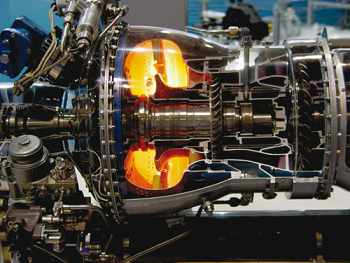
Fig. 2 - Particular of a gas turbine
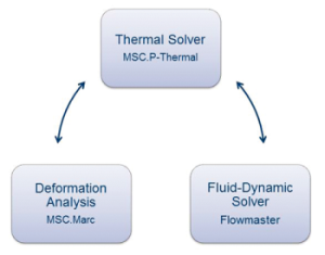
Fig. 1 - Scheme of the integrated multi-physics approach
The temperature distribution in the turbine, indeed, determines deformations in the solid structure which modifies the clearances and, as a consequence, the flow field.
At the same time, the flow field influences the temperature distribution in each turbine component. Moreover, considering that typical diameters of aeronautic turbines are more than 1 m while typical clearances heights are less the 0.5 mm, it is clear that high design accuracy and absolute reliability are required.
For all these reasons, only a numerical multi-physics approach capable to model the entire system early in the design phase and capable to account for fluid-dynamic, thermal and deformational behavior at the same time can guarantee the required clearance design accuracy and reliability.
The Multi-Physics Approach
The numerical multi-physics approach used to simulate aeronautic engines consists is an automatic procedure
developed by AVIO with the help of EnginSoft, as fluid-dynamic solver integrator, capable of managing the operation and
data transfer of three different commercial software:
MSC.P-thermal: thermal solver used for the computation of the temperature distribution in the solid structure;
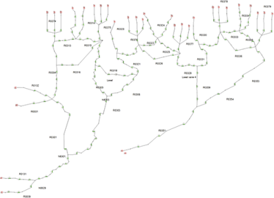
Fig. 3 - Example of a Flowmaster network for the
system level fluid-dynamic simulations
MSC.Marc: deformation analysis tool used for the computation of solid structure deformation;
Flowmaster: system level fluid-dynamic solver used for the computation of the flow field through the gas turbine.
The multi-physics simulation is driven by a specific FORTRAN library implemented into MSC.P-thermal. This library
manages the co-simulation by invoking the fluid-dynamic solver (Flowmaster) and the deformation analysis software
(MSC.Marc) when required. In particular, the call to Flowmaster is managed by a coupling interface procedure
implemented ad hoc in Visual Basic. The coupling interface manages the data transfer between the two codes and manages
the fluid-dynamic simulation in all its parts by setting simulation and component data, running the simulation and
exporting the results.
System Level Simulations
To guarantee the required design accuracy, the entire system needs to be modeled, integrating rotor and static
systems of the entire turbine. In particular all secondary air systems, cooling circuits, active clearance control
devices and the main flow path are to be considered in a system level analysis.
A simulation of the entire engine mission considers idle, take off, cruise, approach and landing phases. A complete simulation lasts about one week and requires about 5000 Flowmaster simulations and about 3000 deformation analyses. All simulations and data transfer are automatically controlled and managed by the thermal solver through the automatic interface procedure as described above.
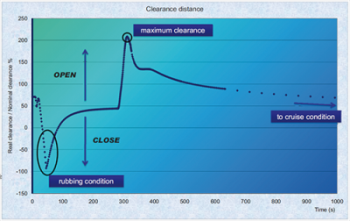
Fig. 4 - Results of an integrated multi-physics
simulation of the entire engine mission: clearance (%)
Conclusions
The implemented numerical multi-physics approach allows to achieve a better understanding of the thermal behavior
of the turbine during the entire engine mission early in the design phase.
This, in turn, allows to define the optimal geometries, materials and cooling mass flows for active clearance control.
In the final analysis, the implemented multi-physics integrated approach, when used early in the design phase, allows to define the optimal clearances capable to achieve high efficiency and, as a consequence, capable to reduce the fuel consumption and to meet the future emission limits.