Using CAE to Optimize the Structure of Power Harrows in Farm Equipment
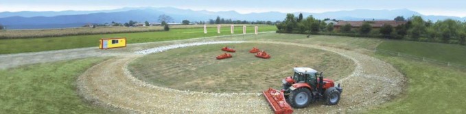
The Frandent company is located in Osasco (TO), a small town near Pinerolo, about 50km from Turin. Since 1977, it has specialized in the design and production of agricultural machines and, in particular, power harrows, tedder spreaders and rotary rakes. In 2006, Frandent started working in a new plant and introduced considerable innovations in its design and production processes, such as the sustainable management of energy consumption. One of the most important investments Frandent has made in innovation is the 15,000 m2 test track it has set up and uses to perform functional experimental tests of its products in both nominal and extreme conditions. Frandent also commissioned EnginSoft to collaborate strongly with its R&D department on its innovation program, which aims to continuously optimize the company’s products to meet the global market challenges of durability and product performance.

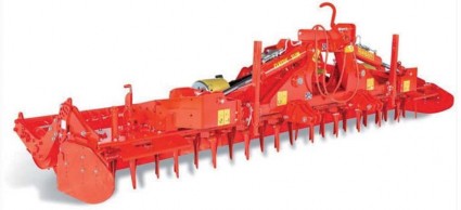
Power Harrow
Introduction
One of the goals of the collaboration activities was to increase the viable working velocity of the harrow since higher speed means less time and, in the highly competitive environment of the global market, this performance efficiency equates to a fundamental valueadd in the customers’ perception. From the technical point of view, the study was concerned with optimizing the strength of the harrow tooth by looking for the best compromise between the mechanical resistance of the tooth and its mandatory function as a failsafe in the overall transmission chain. In fact, as a cheaper and easily replaceable part, the tooth is required to be the first component that breaks in the case of an extreme impact with an object such as a stone, which can easily occur while working the ground.
Virtual Test Description
The simulation represented the impact of the harrow tooth against a stone during the working phase. Using CAE to optimize the structure of power harrows. The test was carried out in different conditions which varied:

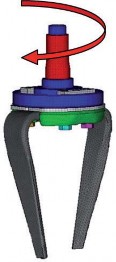
Replaceable Tooth
- the impact point
- the impact angle
- the stone shape
- the rotational and translation speeds ratio
- the severity of the test (from nominal conditions to the most severe scenario)
The impact velocity is the sum of the tractor’s forward translational speed and the tangential velocity of the tooth. Nominal operating speed was also analyzed. Moreover, two different geometries were considered:
- A nominal geometry (corresponding to the CAD output)
- The geometry of a worn tooth and tooth housing.
In order to facilitate the replacement of a broken tooth in the presence of dust and mud, each tooth is mounted with a clearance area. These coupling conditions, however, also allow the surfaces to slide and impact against each other during use and, as a consequence, the clearance area increases during the life of the harrow. As a result, the mechanical behavior of the new and worn tooth geometries differs.
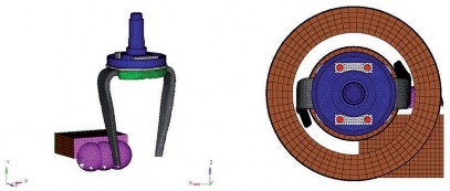
The Complete Finite Element Model
Finite Element Model (FEM)
The FEM was generated using second-order solid elements; in particular, the teeth of the harrow were modeled with tetrahedral elements. The initial conditions were introduced by considering the rigid motion of the support shaft.
In order to replicate the working conditions of the harrow, a foam material model with properties able to reproduce the real phenomena was used to represent the soil. The soil supports the stone at the opposite side with reference to the impact.
The steel constituting the tooth’s material was introduced as *MAT_24 through the stress/strain curves (considering the strain rate).
Finite Element Model of the rotor
To correctly simulate the failure behavior, the engineers implemented a homogenization algorithm. They also introduced and calibrated a nonlocal theory approach (material card *MAT_ NONLOCAL); in this method, the failure criterion considers the state of the material within a radius of influence surrounding the integration point.
An advantage of using nonlocal failure is that mesh size and mesh flow sensitivity on failure are greatly reduced which leads to results that converge to a unique solution as the mesh is refined. Without introducing a nonlocal criterion, strains will tend to localize randomly with mesh refinement, which leads to results that can change significantly from mesh to mesh.
A nonlocal failure theory approach can be very helpful in predicting both the onset and the evolution of the material failure. It renders the failure mesh independent, more homogeneous and more realistic. This method does, however, increase CPU time significantly, so it is wiser to use it strategically.
Results
Model calibration
The model calibration concerned two different aspects:
- soil and stone modeling
- the calibration of nonlocal material parameters
Initially, the working conditions analyzed were not critical and did not lead to tooth rupture; therefore, the soil and stone material models were modified to make the analysis more severe and realistic.
The model had to represent:
- similar conditions of failure to those in the experimental tests
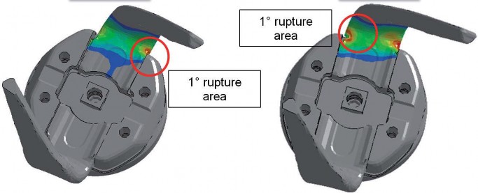
- the initial crack’s position (where the crack starts)
- the crack’s evolution.
The second correlation step was to set the nonlocal material parameters. The values introduced had to guarantee that the initial failure point and its evolution were not affected by:
- the local mesh
- the local mesh size
- the local mesh orientation
As a result, the simulation team was able to create a correlated and robust FE model.
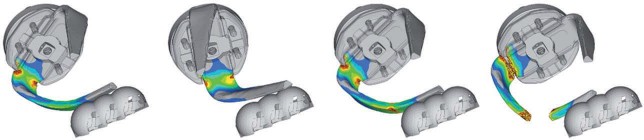
Virtual test results (original geometry)
The analyses on the significant impact conditions for both the new and the worn tooth were then carried out using the FE model calibrated in the previous task. The results (see fig 8) showed that the mechanical behavior is strongly affected by the tooth’s wear; the structure had to be validated for both conditions.
Virtual test results (Optimized geometry)
The tooth geometry was modified with a new design to improve the strength of the tooth but, in the second, optimized geometry simulation, the measured torque during the impact could not exceed the value measured in the original geometry simulation. This parameter was mandatory because the teeth are vital to safeguarding the transmission chain in the case of extreme impacts.
Conclusion
Frandent is transforming itself by increasing its R&D activities in order to deliver best-in-class products. But, these ever-increasing performance improvements have to be achieved in a short time while reducing the high prototyping and testing costs. CAE includes very powerful technologies that are able to simulate real working conditions. It also allows several designs to be evaluated virtually, dramatically cutting the development time and costs. In term of component failure, we confirmed very good correlations between the numerical analysis and the experimental tests. Moreover, the CAE-driven design created a more robust part because it could be tested in all the possible working conditions, without limitations. As a result, Frandent and EnginSoft could define a new tooth geometry that increased the viable working velocity of the power harrow by 12%.
Ezio Bruno, Frandent Livio Airaudi, Danilo Col, EnginSoft