1D-CFD Simulation or System Level CFD
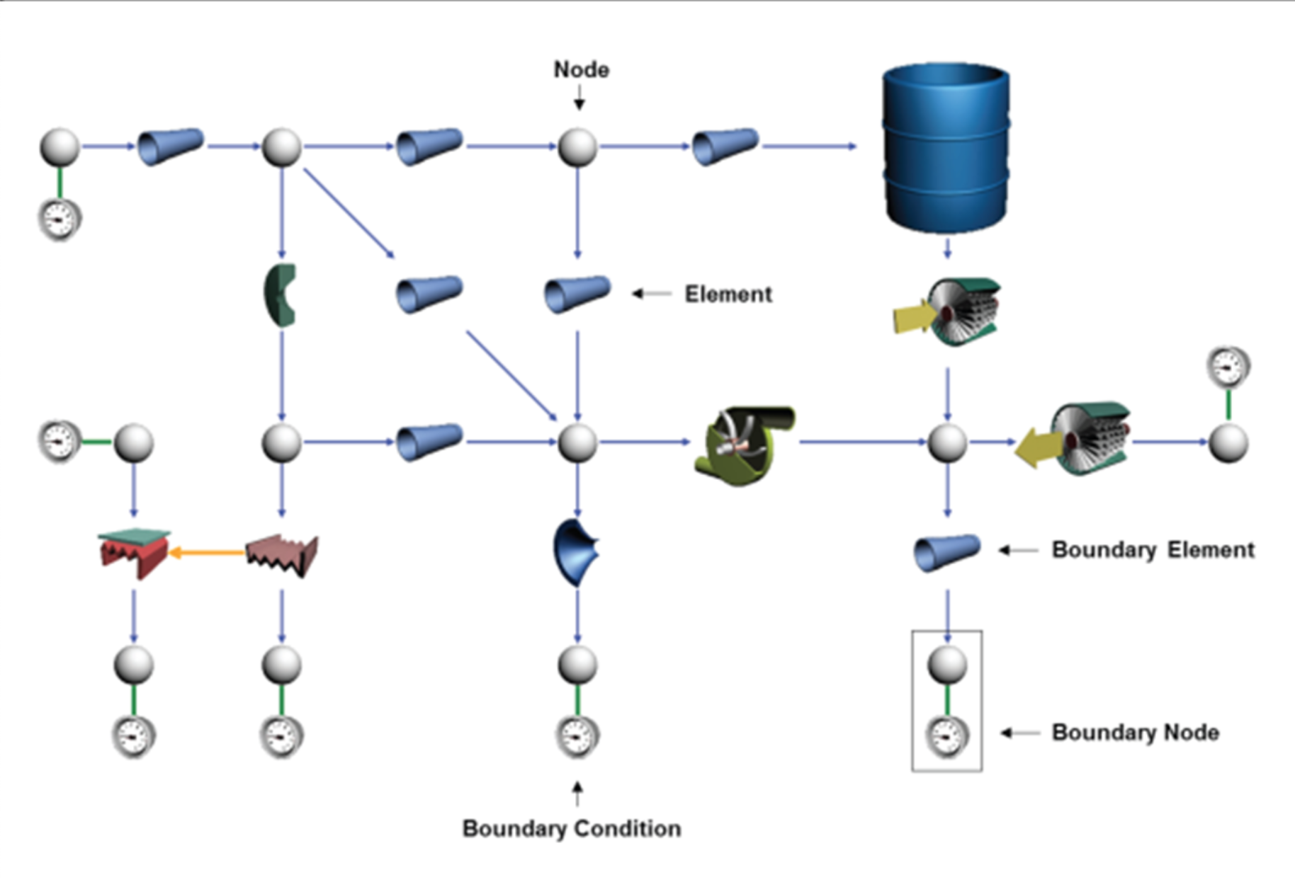
A 1D-CFD simulation or system level CFD focuses on the entire system rather than on the details of the flow inside a specific component of that system. In a 1D-CFD simulation each system component is modeled, and their combined effect is modeled in the systems, uing empirical laws or performance maps.
Industries that can benefit from a 1D CFD Analysis
1D-CFD system modeling can be applied to almost any industrial sector including:
- Automotive: to model the engine cooling, air conditioning, lubrication, fuel and exhaust systems
- Aerospace: to model the environmental control, fuel and hydraulic systems
- Chemical processing: to model cooling, safety and distribution systems
- Energy: to model the cooling, safety and gas turbine systems
- Oil & gas: to model the compressor stations, distribution and cooling systems
Request Demo
System 1D-CFD from the Numerical Simulation Perspective
In 1D-CFD simulations a physical system is modeled using a network of different components each of which models a specific component of the system such as a pump, valve, pipe or bend.
Each component is modeled on the basis of empirical formulae describing the relationship between flow and pressure drops and between flow and heat transfer (if the model accounts for such a phenomenon). Each component is therefore characterized by geometrical and performance data. For these reasons the 1D-CFD software package used must include a comprehensive library of pre-defined components, performance data and materials used for creating and characterizing the network.
In the real world, every system, from a small air conditioning system to a large chemical cooling system with thousands of components (pipes, bends, valves ...), must satisfy prescribed safety and high performance requirements. In most cases it is virtually impossible to test the system before it is actually built. Notwithstanding this, a faulty sizing of the system or a single badly designed component can jeopardize the entire project and for these reasons numerical studies in the pre-design phase of the project are mandatory to satisfy all requirements.
Request Demo
1D-CFD simulations can be:
- steady state, in order to study the performance of a system in equilibrium
- transient, in order to study the response of the system to a particular event
Additionally thermal phenomena can be considered in order to study heat transfer processes inside the system or between the system and the external environment.
1D-CFD and 3D-CFD systems are not used in a mutually exclusive manner. On the contrary they should be considered as complementary systems where particular components in the 1D network can be characterized using data coming from 3D-CFD simulations, and 1D-CFD simulations can be used to identify boundary conditions for 3D-CFD simulations.
Typical physical aspects to be covered in a 1D-CFD system are:
- pressure drop calculations in each component and in the entire system
- flow balancing and sizing of the entire system
- water hammer effect (pressure surge) in transient incompressible analyses
- compressibility, Joule-Thomson effect and wave propagation in compressible transient analyses
- heat transfer in the system and between the system and its surroundings
Why are System Level 1D-CFD simulations so important?
Industrial systems, from the smallest to the largest, must operate in many different scenarios and under different operational and often extreme conditions. Moreover, they can undergo operational and emergency maneuvers such as the pump tripping or valve movements that may cause severe pressure surges (water hammer effect) that may damage the system and cause serious safety issues.
Since it is not possible to test most systems before they are installed, it is of paramount importance that the most reliable design be created in the design phase of the project. Since simulations at a system level take from just a few seconds to a few hours to run, it is possible to test hundreds or even thousands of different configurations, different operational conditions and different maneuvers during the pre-design and design phases. The results provide engineers with a deep understanding of the system’s performances and of the system’s sensitivity to different conditions.
Typical system simulation activities are:
- system balancing and component sizing
- emergency maneuvers (e.g. valve closure) to verify that no cavitation occurs and that maximum pressure does not exceed the maximum allowable pressure
- pump tripping due to a power-off to verify the response of the system to such a failure
- emergency discharge of pressurized vessels to verify the wave propagation and the pressure history in the system
- system warm-up to evaluate the time required to reach the optimal temperature of the system
- transient simulations to evaluate the times required to fill a defined volume


