Multibody Dynamics of an Excavator using RecurDyn
In the past years, the use of MultiBody Simulation (MBS) in industry has progressively grown. This approach is used to investigate both kinematics and dynamics of moving mechanisms, which are composed by multiple bodies interacting with each other through joints and contacts. MultiBody Simulation is the recommended numerical method to quickly complete the following tasks:
- design of mechanisms for motion control (e.g. cams, links, guides)
- check of functionality and performance assessment (e.g. interference check, speed and acceleration analysis)
- estimation of joint loads and internal reactions in transient conditions, in order to choose actuators, brakes and other power devices.
The most basic MBS approach idealizes the system components as rigid bodies. Although sometimes this assumption is fairly acceptable, a high number of applications cannot be virtualized, ignoring the body compliance. Flexibility affects the value of the participating inertia, influences the application points of loads and changes the way the kinetic energy is dissipated in the system. For all of these reasons, different numerical methods have been developed in order to introduce flexible bodies in MultiBody Simulation. Although general guidelines cannot be formulated, flexible MultiBody Simulation is recommended in, at least, three situations:
- when external loads have frequencies close to structural ones (resonances)
- when the system undergoes high speed dynamics and vibrations affect the requested outputs
- when the calculation of stress and strains in transient conditions is a mandatory output of the study
For the types of outputs it provides, a flexible MultiBody Simulation can be assimilated to a transient Finite Element Analysis. The big difference is in the numerical formulation of the two problems, which makes MultiBody a little less precise, but much (much) faster. Moreover, the MultiBody approach, even when it includes flexible bodies, it keeps its distinctive natural connectivity with control system design, pneumatics, hydraulics, and electronics.
RecurDyn, the premium multibody software from FunctionBay Korea, is a key technology in this scenario. It implements two alternative technologies for flexible body modeling. This paper compares the two approaches and highlights the advantages of each one of them.
Case study
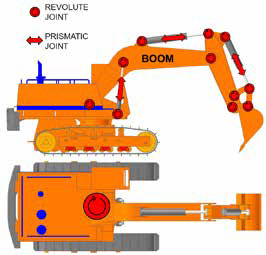
The multibody model of an excavator is chosen as reference case study. The simplicity of this example helps in maximizing the differences between the modeling approaches.
A series of revolute joints connects the arm bodies in a single kinematic chain going from the bucket to the cabin. The latter body is then connected to the vehicle base through one more revolute joint with vertical axis. Three groups of hydraulic cylinders control the arm configuration. Each actuator consists of a piston and a cylinder, coupled together by a translational joint. Both ends of each actuator are linked to the excavator structure by means of revolute/spherical joints. The overall kinematic scheme is fairly simple and represents the degrees of freedom of the actual excavator.
The model is initially built using rigid bodies only. This step is useful to check the appropriateness of joints, drivers, motion functions and contacts. The flexibility is applied to selected bodies in a second phase. In general, it is not necessary to switch all bodies to flexible and, more important, it is not necessary to use the same approach for all flexible bodies. In our example, we will convert just the excavator boom to a flexible, which is the main part of the machine arm.
The simulation reproduces a standard working cycle of the excavator. The bucket approaches a target object (not modeled), digs it, transports it, unloads it and finally moves back to the initial position. All tasks are completed in about eleven seconds. The motion is obtained by governing the lengths of the hydraulic actuators and the angular position of the revolute joint between base and cabin.
Rigid Body Dynamics
The dynamic analysis with a rigid multibody excavator model returns the outputs of Figure 2. The plots show the reaction forces and torques of the revolute joints connecting the boom to the rest of the model.
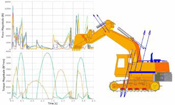 The rigid body simulation confirms that all motion laws are correctly defined. Moreover, the internal reaction loads are perfect inputs for a structural assessment, which has to be carried out using an external FE code. Since the load histories have multiple peaks, generally not synchronized, a complete structural analysis of the boom requires to repeat the FE calculation multiple times. The Figure 3 shows the meshed boom (shell elements) loaded with one of the force and moment set extracted from the multibody simulation.
The loads coming from a rigid multibody analysis are averagely higher than the true ones, because the moving inertia is overestimated. Accordingly, the power demand of the actuators is overestimated. From a structural point of view the procedure is conservative, although it is not easy to rate how much. For mechanisms moving at slow speed (with respect to the first natural frequency of the structure), the two step procedure is fairly applicable. For high speed dynamics, the use of rigid bodies easily leads to excessive loads and, therefore, excessive sizing of the components. Another weak point of this procedure is that two separate codes (Multi-Body and Finite Element) are required. There is always a risk of error in the load data transfer, especially because the multibody loads have spatial components over moving bodies.
Flexible Multi-Body Simulation is an interesting alternative to this traditional approach, which improves the quality of the results and, at the same time, makes the whole calculation process straightforward and easier.
Reduced Flex Technology (RFlex)
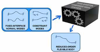
In RecurDyn, the Reduced Flex method coincides with the well-known and widely accepted Craig-Bampton approach. The method was developed at the end of ’70 in the aerospace industry, to reduce the overall size of large FE models. The theory assumes that the response of a flexible body in static (and dynamic) conditions can be represented by a linear superposition of several mode shapes, which is why this approach is also known as Component Mode Synthesis. By doing so, the initial meshed body is translated into a mathematical object whose unknowns are the linear multipliers of the base modes. This results in an evident reduction in the number of unknowns. This theory has been expanded and adjusted along the years, but the original rules are still valid and applied to create flexible bodies in almost every modern multibody software.
Figure 4 graphically describes the RFLex approach in RecurDyn. The modal basis, which will numerically describe the body flexibility, is created by combining two sets of structural modes: the fixed interface vibration modes and the so-called constraint modes. The result is a mathematical object whose unknowns are the multipliers of the orthonormalized modes.
All of these operations require an external Finite Element code, which provides the tools for meshing the geometry and for performing the necessary FE analyses. As all of the competitor software, RecurDyn can import RFLex data from ANSYS and NASTRAN. However, it also includes both an internal mesher and an internal FE solver that make it possible to prepare the RFlex data without the need of an external FE code.
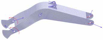
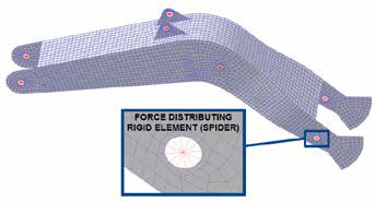
 In our model, the Reduced Flex method is applied to the excavator boom. First the geometry is meshed to obtain a FE model composed by shell elements. The thickness is set in accordance with the starting CAD, while the material is set to steel (linear isotropic properties). In order to establish a physical connection between the joints and the geometry of the flexible body, RecurDyn creates Force Distributing Rigid (FDR) elements (Figure 5). Each FDR element has a master node at the joint center, and a spider of links (could be thought as rigid beams) connected to the scoped geometry. The master nodes always have 6 degrees of freedom (3 rotations and 3 translations), so that the deformations induced by both forces and moments over the structure can be correctly accounted.
First the fixed-interface modal analysis is performed on the FE model. For our problem, we limited the calculation to the first 30 eigenvalues and eigenvectors. There is not a general rule to fix this number normally the user evaluates the mode frequencies and chooses the number in accordance to the higher phenomena he would like to see in the simulation. Then, 48 constraint modes are calculated. This number is obtained by multiplying the number of master nodes (the boom has 8 joints) by the number of Degrees Of Freedom (DOF) of each master node (6). Each constraint mode consists in a static analysis where a unit displacement is applied to a single DOF, while the remaining ones are kept to zero.
 After the pre-calculation phase, we get a total of 30 + 48 = 78 modes. These modes are combined together and orthonormalized to generate the RFlex modal base. Some of the modes included in this mathematical object are shown in Figure 6.
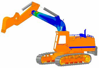
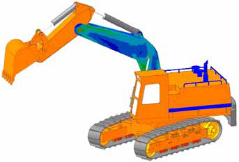
Once the RFlex boom is ready, it is incorporated in the excavator model (joints are automatically connected to the master nodes) and the MultiBody Simulation is performed as usual. Besides the results we got earlier from the rigid multibody simulation, the model now outputs also stresses and strains. These structural quantities are available over the entire boom extension, over all simulation time. This makes possible to easily identify where and when the most critical stress state occurs.
Figure 7 shows the distribution of the equivalent Von Mises stress over the boom deformed body, at the instant where it reaches the maximum value. In our example, the peak is much lower than the material strength. The highest stress is even lower than the fatigue limit, excluding any type of structural problem for this structure. By watching the animation of the results, it is easy to observe oscillations of the excavator arm that were not visible in the rigid multibody results. This is a realistic behavior, which can be easily observed in a true working excavator.
FullFlex Technology (FFlex)
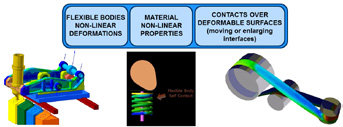
Despite being very well performing, RFlex technology has intrinsic limits that make it unusable in several applications. First, the linear behavior is acceptable for small deformations only. Second, it is almost impossible to properly describe the effects of contacts through a master node interface.
In order to overcome these limits, FunctionBay has introduced in RecurDyn an advanced approach for flexible body modeling. The FullFlex (FFlex) technology is a simplified implementation of the Finite Element formulation. While RFlex method speeds up the solution by reducing the number of unknowns, the FFlex method is based on a smart simplification of the equations that describe the coordinates of all mesh nodes.
A FFlex model keeps all of its native DOFs, but the solution time is terrifically reduced. Every MultiBody Simulation performed with RecurDyn FullFlex technology is equivalent to a transient Finite Element analysis. For this reason, this advanced approach has been called Multi-Flexible-Body Dynamics (MFBD).
The FullFlex technology breaks all limits of the ReducedFlex one. It calculates the structural response of structures undergoing large rotations and large displacements. It also manages large deformations, with the ability to simulate a non-linear behavior of the material. It also makes possible the definition of contacts over the bodies (solids, shells, beams) with no restrictions.
From a numerical point of view, FullFlex models have a noticeable number of DOFs. However, thanks to both the smart formulation of the equations and the power of the hybrid solver, RecurDyn assures very fair computing time.
 In our excavator example the RFlex technology worked just fine and returned reliable structural results. However, the areas where the joints are located are unavoidably affected by modeling approximations. Indeed, the Force Distributing Rigid elements make them rigid and recreate an unrealistic stress state.
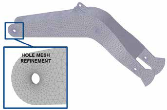
In order to highlight the benefits of the FullFlex technology, we have modified the excavator model and, in particular, the flexible formulation of the boom body. A new solid mesh is created, with specific refinements applied on the connecting areas (Figure 9). FDR interfaces are kept only for the connections of the actuators, whereas non-linear contacts are set between holes and pins on the two boom ends.
 The dynamic analysis of the excavator with this new model returns almost the same structural results we got previously. As shown in Figure 10 the maximum value of the Von Mises stress is still lower than the fatigue limit. From a different perspective, this confirms that Reduced Flex and Full Flex technologies are both reliable.
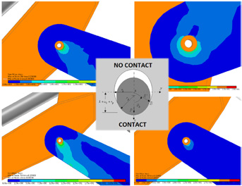
 The Figure 11 provides a significant detail of the Von Mises equivalent stress distribution at the interface between boom and dipper stick. There is a clear subdivision of the hole in two regions: one region is stressed by the pin pressure while the second region is almost unloaded. Such result cannot be captured using the Reduced Flex approach.
Comparison of methods and conclusions
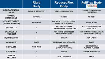
The table in Figure 12 points out the main differences between the three possible approaches to model a mechanical system in RecurDyn. The complexity of the model (and the calculation time) grows going from left to right, as the number of unknowns grows as well. The user should always choose the approach that returns the desired output with the minimum computational effort.
- The most significant advantages of the RecurDyn Full Flex approach can be summarized as follows:
- modeling of body connections in a very realistic way, without introducing any local stiffening spider
- large deformations, large rotations and large displacements are natively taken into account
- it is possible to use both linear and non-linear materials
- there is no limit in the use of non-linear contacts between flexible bodies. They can be set between solid, shell and beam elements
- the simulated dynamics of flexible bodies is exact, because it is no longer the output of a transfer function based on selected vibration modes (Craig-Bampton approach).
 For all of the above reasons, RecurDyn is the most powerful and most versatile software in the market, designed to perform flexible multibody simulation.