The Simulation Capabilities of Creo
Using digital prototypes to understand how your designs perform in real-world conditions is vital to your product development process. Not only can you reduce costly physical prototyping, but you can also increase your products durability, reliability, and safety. Nobody enjoys product recalls after all.
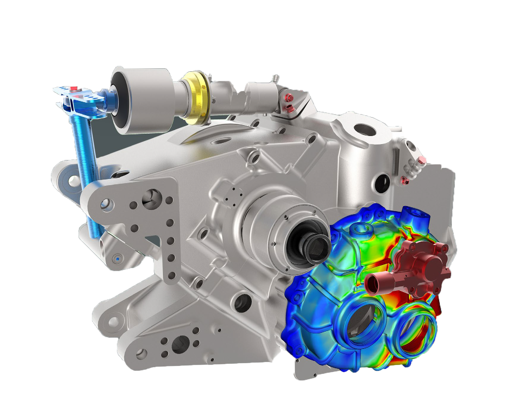 We understand why most designers do not want to use simulation software. You are engineers not analysts! For too long, simulation software has been hard to use, time consuming, and difficult to integrate with CAD data. But, with EnginSoft and PTC’s simulation software you don’t need a PhD to get accurate results fast.
PTC’s simulation software is designed uniquely for the engineer, complete with the common Creo user interface, engineering terminology, and seamless integration between CAD and CAE data, allowing for a more streamlined process. Best of all, the results are accurate and reliable and can be easily calculated with very little input from non-simulation experts.
The family of simulation software is a complete structural, thermal and vibration analysis solution with a comprehensive set of finite elements analysis (FEA) capabilities that allow you to analyze and validate the performance of your 3D virtual prototypes before you make the first part.
Finite Element Analysis
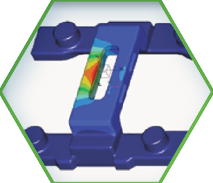
- Understand the response of your design when subjected to various loading conditions
- Integrated seamlessly with the Creo 3D CAD environment
- Automatic checks to ensure robust and reliable analysis results
- Comprehensive materials library provided
- Fully automatic mesh generation directly on 3D CAD geometry
- Units of measurement are managed consistently throughout the application
Static Structural Analysis
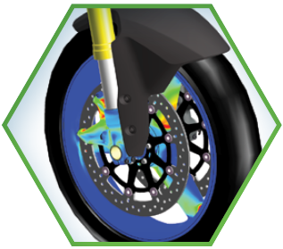
- Determine accurate stresses, strains and displacements in your product
- Conduct linear static analyses
- Loads and boundary conditions are easily applied and use engineering terminology
Automatic Meshing

- Create accurate meshes directly on 3D CAD geometry
- Meshes follow highly detailed and curved geometry precisely
- Automatically update and refine meshes to ensure accurate simulations
- Supports solid (tetrahedron, wedge, hex), shell (triangle, quad), beam, spring, mass elements
- Flexibility to define element sizes, distribution and shapes (mapped meshing, thin solids)
Modal and Buckling Analysis
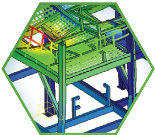
- Determine natural frequency modes of vibration
- Automatically handle rigid mode (unconstrained) cases
- Determine buckling loads or solve unstable snap-through problems
Design Optimization
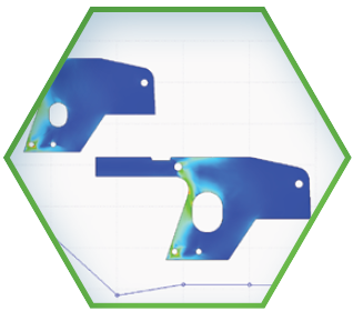
- Clearly understand the impact of design changes
- Reduce product costs by optimizing your design to meet multiple objectives, such as maintaining a product’s strength while reducing its weight
- Save time by automatically iterating your design to meet your design requirements
- Reduce errors by using the results from external tools to drive your design directly, without manually transferring data
Nonlinear Analysis & Large Deformation
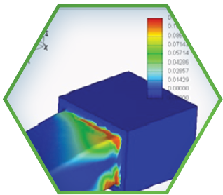
- Easily define elasto-plastic materials and hyper-elastic materials
- Perform nonlinear static structural analysis • Time varying loads
- Understand residual stresses in the model
- Large deformation of thin/slender products
Mechanism Dynamics
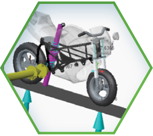
- Determine reaction forces in mechanism design
- Ability to include gravity, springs, dampers and force-based drivers
- Define cam/follower connections between parts in the mechanism
- Automated transfer of MDO results to Structural Analysis to evaluate stresses in the mechanism
Tolerance Analysis
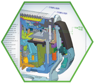
- Evaluate the impact of tolerances on the manufacturability of designs
- Tolerance stack-ups
- Automatic validation of dimensions and dimension loops
- Graphical display of statistical distributions
- Contribution and sensitivity output plots